 Michael D. Adkins, Swagelok Company, examines ways in which to flatten pressure-reducing regulator flow curves in high-flow systems. He shows how adding external components, and making internal design changes, to the domeloaded regulator can improve performance
When an application calls for maintaining consistent downstream pressures at high flows, it will most likely require the use of a domeloaded pressure-reducing regulator. Even then, you may need to add external components to the regulator to achieve your desired performance. Your goal in doing so is to produce a reasonably flat flow curve for the regulator at a set pressure.
A flow curve for a pressure-reducing regulator illustrates the range of outlet pressures (vertical axis) the regulator will maintain based on various flow rates (horizontal axis) in a system. Ideally, you want to operate the regulator on the flattest – or most horizontal – part of a curve, which is where it will maintain relatively constant pressure even with changes in flow.
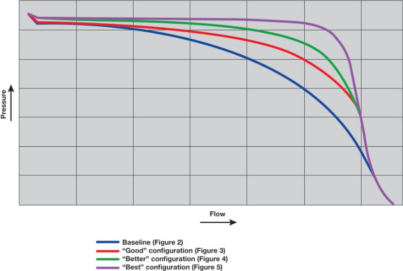
 Unfortunately, every pressure-reducing regulator flow curve will experience some droop. Figure 1 represents four flow curves, and as you read each one from left to right, the downward slope in pressure is referred to as “droop.” On the far right of each curve, you can see where pressure drops steeply. The point from where the pressure begins to decline rapidly to where it approaches zero is called the choked-flow area. You want to avoid operating your regulator in this region because it will result in a relatively large pressure drop downstream. This is the region where your regulator is not efficient or effective. If your flow rates will take you into this region, you should consider a different or larger size regulator.
However, when operating a regulator in the functional portion of the curve (e.g., before the choked-flow area begins), you can reduce droop and achieve a flatter curve across a wider flow range by expanding the regulator’s capabilities. Using a springloaded regulator as a baseline (Figure 2), this article will explore the following system configurations:
1. Employ an upstream pilot regulator to control dome pressure in a domeloaded regulator (Figure 3);
2. Employ an upstream pilot regulator and add downstream external feedback to the domeloaded regulator (Figure 4); or
3. Employ an upstream pilot regulator and add downstream external feedback to the pilot regulator (and not a domeloaded regulator) (Figure 5).
These configurations offer good, better, and best performance in terms of maintaining more consistent pressure – and therefore flatter flow curves – over increasingly broader flow ranges.
 For this article, we’ll focus our attention on a facility that uses nitrogen from a single source for multiple processes. Assuming that the processes are not all in continuous operation, nitrogen flow demand will vary throughout the day. If the facility were to employ a springloaded regulator to control gas pressure, an increase in downstream flow would cause pressure drops, while a decrease in downstream flow would cause pressure spikes. Both pressure changes would require frequent manual adjustments to the regulator or additional point of use regulation. Instead, the facility will use a domeloaded regulator, which enables dynamic pressure control – without manual adjustments – to provide more consistent pressure as flow demands vary.
 In a domeloaded regulator, a volume of pressurized gas in the regulator’s dome chamber replaces the role of the spring in a springloaded regulator. The dome chamber is pressurized at a level just above the required outlet pressure. This constant pressure creates a force on top of the diaphragm. If that force is higher than the force created by the outlet pressure, the poppet will open. As pressure equalizes, the downstream pressure will apply a force upward on the diaphragm to close the poppet.
 Adding various external components, and internal design changes, to the domeloaded regulator enables pressure on the dome to be adjusted dynamically to improve performance.
‘Good’
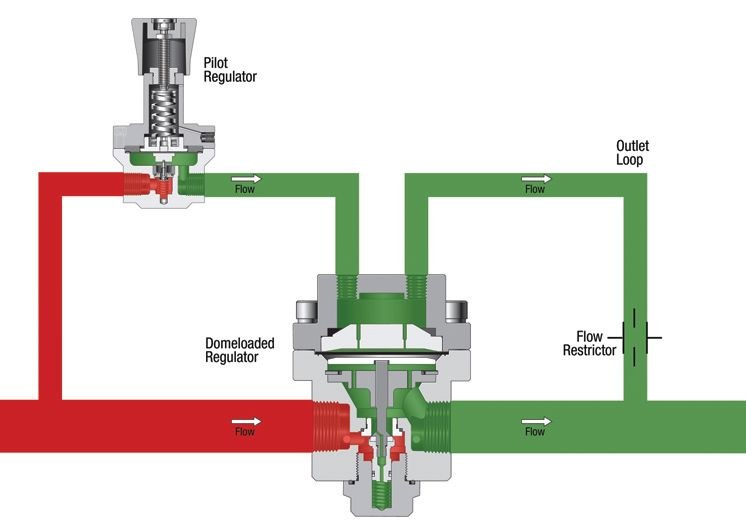
In the “good” regulator configuration, we’ll employ a domeloaded regulator that responds to pressure fluctuations by enabling pressure in the regulator’s dome chamber to remain constant over a wider system flow range. To allow this, we’ll add a pilot regulator to deliver pressurized gas to the domeloaded regulator’s dome chamber, as well as an outlet loop to relieve excess dome pressure (Figure 3). This setup provides dynamic dome pressure control to help the domeloaded regulator maintain its initial set pressure.
The second flow curve in Figure 1 shows the extended capabilities the domeloaded and pilot regulator configuration enables compared to the system using a springloaded regulator (curve 1). The set spring in a springloaded regulator loses force when it gets longer when pushing the poppet open. This causes the droop (drop in outlet pressure). With dynamic dome pressure control provided by the pilot regulator, the useable area of the flow curve is greater compared to the springloaded regulator. Depending on the specifics of the application, the “good” configuration will allow for use on systems with increased flow without worry of experiencing significant outlet pressure drops. But, we can do better.
‘Better’
In our second – or “better” – configuration, we’ll add a feedback line to enable the domeloaded regulator to compensate for downstream pressure drops. Using the same pilot regulator and outlet loop setup, we’ll incorporate a downstream tubing run that delivers external feedback to the sensing area of the domeloaded regulator (Figure 4). This configuration flattens the curve.
Looking at the third flow curve in Figure 1, you’ll notice that the curve is flatter for this “better” configuration. Remember, we’re using the same domeloaded regulator, with modifications to the sensing area, set to the same outlet pressure for the second, third and fourth flow curves. In addition, you’ll see that the operating flow rate of the regulator has expanded before reaching a choked-flow state. However, we can still do better.
‘Best’
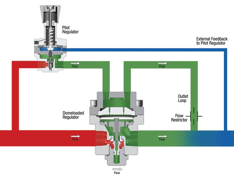
The third system configuration – our “best” scenario – enables the pilot regulator to make highly accurate adjustments to pressure in the domeloaded regulator’s dome chamber based on the actual downstream system pressure. Like the “better” configuration, this design employs a pilot regulator, an outlet loop to relieve excess dome pressure, and an external feedback line. In this setup, however, the downstream tubing run delivers external feedback directly to the pilot regulator (Figure 5). With adjustments made at the primary pressure control source – the pilot regulator – this configuration maintains very precise control of downstream pressure and yields a very flat flow curve over a very broad flow range.
This system configuration creates a loop that enables constant, automatic adjustments to stabilize the system at the desired set pressure for optimum performance. The results are evident in the fourth flow curve in Figure 1, which is very flat – with almost no droop – over a broad flow range. This system will not experience choked flow until flow climbs even higher. The only way to produce an even flatter – almost perfectly flat – flow curve is to replace the manual pilot regulator in this configuration with an electronically-controlled pilot regulator.
Swagelok