 Syngenta’s Huddersfield production site is using a safety instrumented system (SIS) from Siemens that is based on the integrated approach inherent in the site’s existing PCS7 process control technology. This means common engineering tools can be used, reducing training and spares-holding and simplifying maintenance
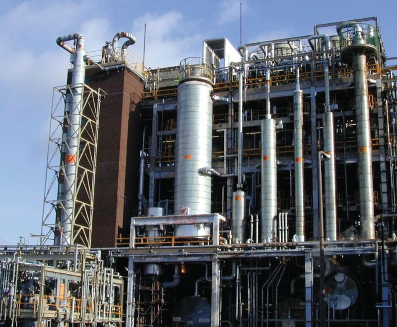
Agribusiness Syngenta makes crop protection active ingredients, such as herbicides, insecticides and fungicides, at its site in Huddersfield. These are typically produced using complex multi-stage batch chemical processing. Such processes, are, in some cases, hazardous and the site is therefore designated as COMAH top tier. The site has an excellent safety record and the management team are committed to maintaining this status.
 For a typical plant on this site the requirement is for up to 40 SIL1 Safety Instrumented Functions (SIFs) and possibly 1 or 2 SIL2 SIFs. The existing hardwired systems are typically enunciated on a dedicated alarm panel. The legacy Basic Process Control System (BPCS) on each plant acts as a layer of protection to reduce the demand on the hardwired safety systems although, in practice, a conservative approach is taken with only a small amount of credit for the risk reduction provided by the BPCS being taken. Traditionally, the hardwired trips have been seen as a backstop for the automation layer; any problems with automation and control might lead to production loss or damage to equipment, but would not have an impact on safety because the hardwired trips provide effective, independent protection.
Against this background of strict separation, the decision to move to a more integrated control and safety system was taken, especially as the automation engineering group were to take on the responsibility for the Safety Instrumented System (SIS).
However, the existing safety systems for the plant were considered to be becoming obsolete. Mick Pearson, automation manager for the Huddersfield site, said: “To achieve the safety requirements using established hard-wired safety logic would have required far more design time and would have resulted in a complex and high maintenance design. To achieve a simpler design to the same safety level at no extra cost through integration with the site’s existing PCS7 automation systems for engineering and visualisation made good sense.”
The site’s license to operate depends on having appropriate safeguards in place and also having a testing regime to ensure the trip systems will work when a demand occurs. In the past, testing of trips on plant was done jointly by operators and instrument technicians on a routine basis. Any replacement system needed to be as easy or, preferably, even easier to test and should support testing activity by offering suitable bypass and override capability so it could be undertaken in a controlled and documented manner. Integration with the Siemens PCS7 Operator Stations allowed any necessary Bypass actions to stand out on the system mimics.
Before the safety upgrade project, the plant used Pressure Relief Mechanical valves as a key component of the ‘Basis of Safety’ to maintain a pressure ‘bubble’ – thus ensuring there is always a positive pressure on the plant vessels to exclude oxygen from the system and so rule out the potential for a flammable atmosphere. However, because there was concern that this system was unreliable, the decision was made to replace the mechanical relief valves.
The existing safety systems used on the plant were increasingly expensive to maintain and it was difficult and expensive to keep engineers trained on the outdated technology.
As the plant used a Siemens PCS7 control system it made sense to utilise the already available, integrated safety capability of PCS7 for the new SIS. It was decided that a new safety controller would be added and this would be ‘owned’ by the site’s automation group. The automation systems on site are customised to meet the requirements of complex batch chemistry so the engineering team wanted to ensure that the Safety PLC was distinct from the existing systems and required no special configuration. For this reason the Safety Matrix tool was selected as a means of minimising ‘programming’, maintaining separation and, as a result, making the verification, validation and audit process more straightforward.
Despite PCS7’s capability for integration of control and safety down to controller level, Syngenta chose to go down the conventional path of not mixing safety functions and control functions within a common CPU. Similarly, a decision was made not to mix safe I/O and standard I/O within a single I/O rack.
The PCS7 system has an integrated approach to safety so that safety applications can be implemented within the same overall system. The use of common engineering tools means reduced training and spares holding and simplified maintenance. In addition, the cost of engineering is reduced because data can be more readily passed between the control and safety instrumented system without additional hardwiring or configuration of communications.
Syngenta’s site engineers could see the benefits of the Safety Matrix cause and effect tool used within PCS7. As the tool generates the safety system logic directly from a cause and effect format it essentially involves a configuration exercise which doesn’t require programming. It reduces engineering and testing time and minimizes the risk of errors.
Importantly from Syngenta’s point of view, it will make subsequent change management simpler because the cause and effect documentation used within the engineering environment is always the master document and forms the basis of the safety logic and the associated operator displays.
Site engineers were keen to ensure that programming was minimal and, thanks to safety matrix, this has been the case. Also, the integrated nature of the engineering tools helps reduce cost and minimise the learning curve for the new system.
One of the key benefits achieved from an integrated approach to the upgrade to the safety system was better visibility for the plant operators.
The intuitive nature of the system helped to ease the transition from the previous non integrated approach and meant that the safety interlocks were easier to manage. The flexible alarm handling also helped address the challenge of system acceptance.
Safety critical trips and interlocks are displayed in a cause and effect format in the Safety Matrix Viewer which gives an intuitive way of assessing the status of the safety system. The ability to integrate the real time and historic data from the safe and non-safe systems benefited day-to-day operations and the analysis of historical performance.
The case and effect operator ‘view’ is again generated automatically within the safety matrix engineering tool, which again reduces the possibility of systematic errors which can creep in during custom configuration of graphics and mapping of data points.
Pearson concluded: “We now have robust and proven technology for this duty and a clear way forward for future safety requirements. The design process results in systems that are easier to understand both for engineers and process operators. Safety Matrix Viewer ensures the safety configuration is easily visible without any difficult software programming.”
Siemens Industry UK
T: 0845 770 5070