 The numerous health, safety and hygiene standards for the chemical, food, and general processing industries, in the USA and Europe in particular, mandate the need for enclosed conveying systems for dry bulk solids, additives and ingredients in whatever form – powders, granules, flakes, pellets and so on.
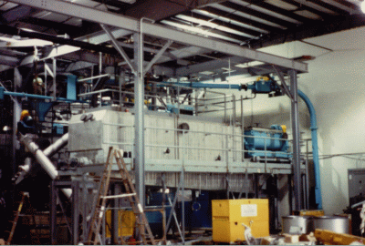
When considering equipment to transport finely divided, flowable bulk materials, the mechanical tubular chain/cable drag conveyor should always be considered. This is truly a “problem solver in a pipeline” and is a concept that, while often overlooked and by the food industry in particular, has been serving a wide range of industries for well over 50 years. In addition to the food and chemical industries, it has found application in the waste water treatment, minerals, brick-making, cement and glass industries too. Design and construction can vary enormously to reflect the demands of the duty to be performed.
 HOW IT WORKS
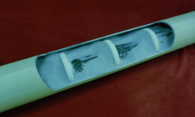
The tubular chain/cable drag chain conveyor is comprised of a stationary outer housing, usually round in shape, through which a chain/cable is pulled by a sprocket. Round conveying flights of a diameter slightly smaller than the inside diameter of the casing are attached to this chain/cable assembly at fixed intervals. As this endless chain/cable assembly is pulled through the casing by a sprocket bulk material is pushed from the feed sources to the discharge points by the conveying flights. This process is all mechanical. No compressed air, blower or filter system is required.
The conveying rate is established by varying the casing diameter and/or the chain/cable velocity. Conveying capacities with this type of equipment can reach as high as 0.5m3/min (20ft3/min), which will satisfy the needs of most processing equipment as well as the needs of general industry.
 The conveyor casing (stationary outer housing) is made from carbon steel or stainless steel pipe and typically available in 80mm, 100mm, 150mm, 200mm and 250mm (3”, 4”, 6”, 8” and 10”) sizes. The casing sections are furnished in lengths up to 6m (20’-0”) long, as dictated by the required conveying path, and are supplied complete with welded steel flanges at both ends, or pipe couplings – according to conveyor type and duty.
To allow the conveyor path to change directions the conveyor casing is formed into a sweep radius elbow, at whatever angle is required, and steel flanges are welded to each end. The straight casing sections as well as the casing bends can then be combined with gaskets and bolted together in the field to form rigid, dust tight joints.
TOTALLY ENCLOSED, DUST-TIGHT
The single most significant feature of this conveyor style is the enclosed construction. This conveyor operates within the confines of a pipeline and is inherently dust tight. This design effectively contains the material being conveyed, along with its dust, to protect the atmosphere and personnel from any adverse 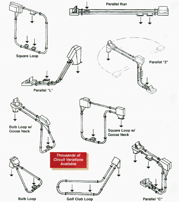 effects from dusting. It also protects the bulk material from contamination from the outside atmosphere and moisture. If required, this equipment can be operated under a light vacuum, positive pressure or product can be conveyed under a blanket of inert gas, such as nitrogen.
Although predominantly designed for dry materials, Tubular Chain/Cable Drag Conveyors are equally adept at conveying moist and wet materials too. Running along the bottom of a settling tank this style of conveyor can collect fines as they precipitate from the fluid in a tank and elevate them above the fluid level to a waiting vessel or piece of process equipment. In the process of elevating the fines there is a natural de-watering effect, via gravity, which could enhance the process at hand. The enclosed construction serves well in containing odors and free moisture that may be present with some sludges and slurries.
THE CHAIN/CABLE ASSEMBLY
At the heart of every tubular chain/cable drag conveyor is the chain/cable assembly, which is the single most critical component in the system.
A chain assembly is comprised of a series of links and pins. A quick examination will indicate that the chain will readily flex with the direction of the chain pin but this is only partially true. A tolerance designed into the pin and link connection points allows the chain to rotate out of plane in any direction. For heavy duty applications (minerals and cement etc) a chain assembly of the pin and link style is the preferred mechanism to move the flights for several reasons: first of all, the sprocket meshes directly with the chain to provide positive movement. Friction type drives are unpredictable and they may slip if the infeed rate surges or if the conveyor take-up is out of adjustment. Sprockets that drive to the flights instead of the chain could develop problems if the lug or hub of a flight shifts, thereby destroying the continuity of flight pitch and resulting in component damage and system  failure. The flights do not have adequate long term durability to withstand the forces normally required to operate this type of conveyor on heavy applications. It is therefore very important that the sprocket engages directly with the chain assembly.
Pin and link style conveyor chains are less prone to fatigue, wear and stretch than steel ropes or ball-and-socket style chains. As wear occurs or if an individual component is somehow damaged in a pin and link style chain assembly, each individual part can be replaced.
Conveying flights can be made of a wide range of materials from the latest grades of UHMW polyethylene, nylon, polyurethane or even cast iron, steel, stainless steel or aluminum. The particulars of every application will determine the appropriate flight material.
CONVEYOR CONFIGURATIONS
A virtually unlimited variation of conveyor circuits is possible, by virtue of the flexible chain design, custom casing lengths and casing bends. These conveyors are manufactured in modular form with bolted flange connections for easy erection in the field. Figure 4 shows a few common configurations and there are thousands of other variations possible. This type of conveyor can be installed in existing facilities bypassing obstacles that would interfere with the paths of other types of conveyors.
 Most commonly this type of conveyor is used to transfer material less than 30m (100 ft) and involve only one or two directional changes. However, transfer distances of several hundred feet are well within the capabilities of this conveyor style.
INLETS
A conveyor inlet is created by removing a short upper half of the conveyor casing and flaring out with sheet metal to make a hopper. Numerous inlet points can be incorporated in a single conveyor. As a general rule material can be flood or surge fed at these inlet points. The conveyor chain/cable assembly will fill with product as it passes below the inlet opening. There are a few very difficult materials that will not self-feed with this style of conveyor. In those few cases, a flow assist in the form of a vibrator, mechanical agitator or an air pad will resolve the flow problem.
OUTLETS
Free-flowing materials
A conveyor discharge is substantially identical to an inlet hopper except that its position is inverted. When the chain and bulk material reach an opening in the casing the bulk  material will flow from the chain through the opening. Multiple discharge points can be built into a single conveyor. In such cases, if control of the discharge point cannot be left to a simple open style discharge, then gate or butterfly valves can be used to select from which outlet material is to be discharged. Discharge from the open bottom of the conveyor drive box housing or idler box is not at all uncommon. The action of the conveyor chain changing direction as it runs around the drive or the idler sprocket has a beneficial flow promotion effect.
Difficult products
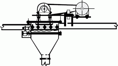
Many free flowing materials will readily flow from the conveyor casing and chain/cable assembly at a discharge point. If it is imperative to your process that you get a complete discharge of material, if the product has sluggish flow characteristics or is sticky, a special chain vibrator is used. This mechanism is comprised of a fractional kilowatt/horsepower electric motor driving through a v-belt to a shaft with adjustable eccentric weights, which is mounted on a spring plate, external of the conveyor. From this spring plate two shafts then penetrate the conveyor housing through sealed openings to connect to a flat bar that will in turn impart a controlled, low frequency vibration directly to the conveyor flights as they pass over a discharge to effectively induce the product to flow from the conveyor. This mechanism is extremely effective on even the most stubborn materials.
THE BENEFITS
No segregation of mixtures
The positive displacement action of this conveyor makes it ideal for handling blended materials without separation.
Gentle conveying action
The slow moving chain assures gentle product handling with an absolute minimal of attrition.
 Reliable/long service life
The slow moving chain, with its robust construction assures long service life, , low maintenance and a very high degree of reliability.
Low noise
The equipment operates at a minimal noise level. In most applications it is difficult to hear the conveyor operating.
Wide temperature range
With cast iron flights and chains, tubular chain/cable drag conveyors will not only handle materials up to 230oC (450oF), they can be used to deliver materials to furnaces and the like.
Low energy consumption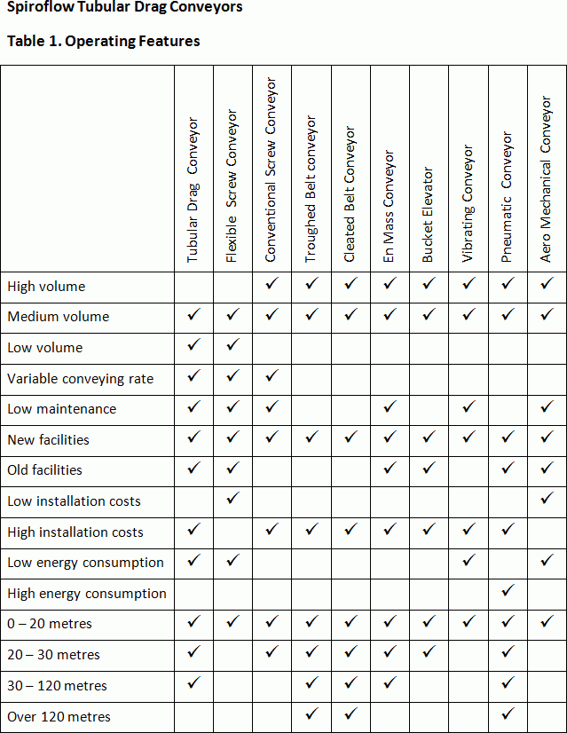
Energy consumption should be a key factor in equipment selection as the ever rising cost of energy is a key component in the overall cost of purchasing and operating the equipment. Due to the slow-moving nature of the tubular chain/cable drag conveyor the power requirement is very low. In many applications, when compared to less energy efficient conveyor types, this equipment can pay for itself in a short period of time based on energy savings alone. A typical tubular drag chain conveyor is operated by a single low kilowatt/horsepower drive motor, usually in the 0.75 to 3.75 kw (1 to 5 HP) range. This fact makes it one of the most energy efficient conveyors available.
No dust filtration system
The tubular chain/cable drag conveyor is all mechanical and does not require the addition of any air; compressed or otherwise. It is ideal for handling hygroscopic materials either with or without dry air or inert gas blanket. And because there is no air added to the system there is no need for product/air separation equipment at the discharge points. More significantly, there is no need for an expensive baghouse filtration system and no loss of valuable or toxic material in the form of collected dust.
Custom designs
As a custom design and build piece of equipment special features can be added to the system to enhance the operation. Examples would be water jackets to cool or heat the casing, cooling fins, pipe insulation, drains or purge connections.
Choosing the correct conveyor
In selection of the type of conveyor best suited to your application you should consider:
 – The various characteristics or qualities of the product to be conveyed.
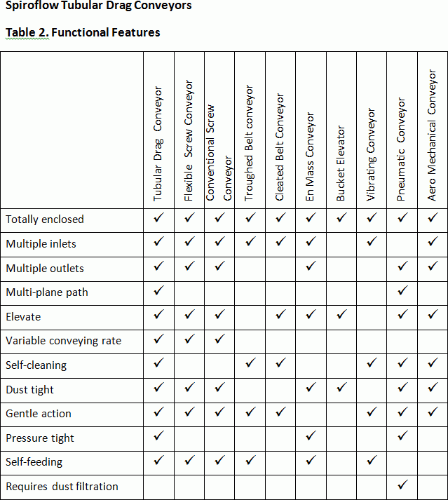
– The performance and functional features required by the process.
– Operating features desired.
– The projected duration of the process or operation the equipment is to serve.
– The long term energy requirements of the equipment.
Figures 10, 11 and 12 show a general comparison of different types of bulk handling conveyors. These charts are intended to help you in your evaluation process. As with all generalizations, there are exceptions to the rules and, accordingly, these charts are for guidance only. The final choice of conveyor must be made in conjunction with your chosen supplier.
Choosing the supplier
There is always a danger in working with companies who only offer one type of conveyor. Unless your application is a real ‘no, no’, there is always the tendency that they will make ‘one size fit all’ and, although the conveyor may actually perform on the duty specified, it may not be the lowest cost, operationally efficient and lowest running cost unit that you could have bought. So, always look for a supplier offering a wide choice of conveyors, one with a proven track record, one that can supply references, one that has a test facility and, above all, one that will offer a process guarantee.
In conclusion
The totally enclosed, mechanical tubular chain/cable drag conveyor will satisfy the demands of a wide range of bulk material handling applications. Low energy cost, low  maintenance cost, easy installation, elimination of the loss of expensive product through dusting, combine to make this conveyor economical to own and operate over the life of the process being served. With its features and benefits this style of conveyor should be considered for every bulk transfer project. Proper equipment selection, with due consideration to the initial costs plus the long term operating costs, will save time and money by improving the efficiency of your operation.
About the author
Robert Sutton has a total of 42 years in the design, manufacture, marketing and application of tubular drag conveyors. In 1980 he started his own business Dynamet Inc based in Kalamazoo, MI, USA. Spiroflow Systems In of Monroe, NC bough the business in 2010 as part of its strategic goal to expand its range of conveyors for dry bulk solids. According, Spiroflow offer one of the widest choices of conveyor in the business including Flexible Screw, Aero Mechanical, Vacuum and Tubular Drag types. Robert Sutton has been retained by Spiroflow as their Global Product Specialist for Tubular Chain/Cable Drag Conveyors.